The Magnetron Part Two
|
A little of the Physics involved…
When a large voltage is applied at the Cathode and a strong
magnetic field is applied across the device, the electrons emitted
at the cathode take a spiral course and a 'vortex' is created
at each cavity. The copper anode begins to resonate, much like
a tuning fork. By accurately controlling the (pulsed) voltage
and the magnetic field it is possible to make the magnetron
oscillate at the correct frequency and at high power. This in
turn produces the radiated microwave radar pulse.
The first laboratory examples produced an output of 400 watts
(at 10 cm wavelength) and within a few weeks this had been boosted
to 1000W. GEC were then contracted to 'clean up' the design
and get them into production. An example of the pre-production
batch was delivered from GEC to Worth Matravers on July 19th
1940. |
| |
|
|
|
| |
|
|
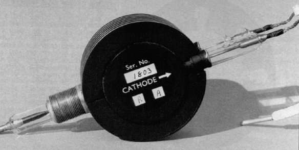
A typical specification for an aircraft
Magnetron like the one above might read thus….
|
| |
|
|
ATTRIBUTE
|
VALUE
|
|
Diameter
|
4inches
|
|
Input Voltage
|
14000 Volts
|
|
Input Current
|
9 amps
|
|
Magnetic Field
|
1350 gauss
|
|
Output Wavelength
|
9cm
|
|
Peak Pulse
Output
|
25kW
|
|
Output Time
|
0.000001 secs
|
|
Pulse Repetition
Freq
|
appx 1000/sec
|
|
Valve Efficiency
|
70%
|
|
Anode
|
Copper
|
|
Cathode
|
Tugsten oxide
coated
|
|
Cooling System
|
Water cooled
|
|
(in production)
|
Air cooled
|
|
| |
|
|
|
| |
|