
|
|
| |
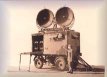
This section aims to provide a basic explanation of how the Wireless Set No.10 functions. If you require a further description of any of the terms used in this section, use the links to the glossary for a lay interpretation. Points considered particularly significant are expanded upon in the reference section. Overview of how the WS10 operates The sending of information using the Wireless Set No.10 involves two phases of operation. For explanation, equipment itself can be divided into two separate parts which in combination achieve the overall transmission. The pulser unit modulates the eight available speech channels into electrical pulses of rectangular wave form. To provide a multi-channel capability, the designers of the WS10 – some of whose own recollections have been used in the construction of this site – developed an ingenious system now know as Time Division Multiplexing. In brief, this is transmission of multiple packets of information on one radio wave by separating them with respect to time, what is called a width-modulate pulse. These rectangular shaped pulses are delivered to an ultra-high-frequency (UHF) sender unit and used to modulate a radio wave, the method by which the data is sent. By the
standards of the 1940s, the WS10 produced radio waves with a revolutionary
technique, using a magnetron. This component
creates short-wave energy by conducting very high voltages within a strong
magnetic field. The energy generated is harnessed by positioning the magnetron
in a cavity that can be tuned by an adjustable piston to resonate at a
frequency which causes the magnetron to oscillate. These resulting waves
are then ‘fed’ with width-modulated pulses. The output of the
sender unit is coupled to a 2” flexible wave-guide on the end of
which is a 4ft diameter parabolic aerial. The energy produced was considered
low-power even by 1940s standards, but the following extracts illustrate
precisely how much energy could be produced by a magnetron.
The sender station transmits
its signal to the known location of the receiver, done simply by use of
a map and compass. Once in place, the WS10 was in constant operation,
ready to receive incoming signals on predetermined frequencies, which
varied according to the type of magnetron value used.
|
.jpg)
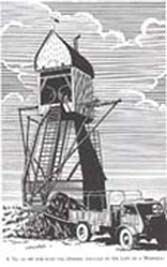 The
image to the right gives an idea of where sites might be located. In the
absence of the standard 60ft tower to which the dishes could be attached,
this windmill outside Eindhoven made a suitable alternative. The reflecting
dishes were removed from the trailer and passed up ladders to the roof
and hidden from sight. The flexible
The
image to the right gives an idea of where sites might be located. In the
absence of the standard 60ft tower to which the dishes could be attached,
this windmill outside Eindhoven made a suitable alternative. The reflecting
dishes were removed from the trailer and passed up ladders to the roof
and hidden from sight. The flexible