|
Reception and channel separation
 To
ensure the delivery of the correct information to the correct recipient,
the signals that have been received must be separated, demodulated and
routed to the appropriate telephone line. As mentioned briefly already,
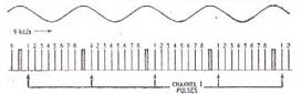
the receiver relies on a synchronisation pulse
to initiate the separation process at the receiving end. This signal is
of significantly longer duration (in electrical terms) than the channel
pulses and is received by the aerial mounted on the roof of the receiver
station. A train of these signals can be seen in the diagram. To
ensure the delivery of the correct information to the correct recipient,
the signals that have been received must be separated, demodulated and
routed to the appropriate telephone line. As mentioned briefly already,
the receiver relies on a synchronisation pulse
to initiate the separation process at the receiving end. This signal is
of significantly longer duration (in electrical terms) than the channel
pulses and is received by the aerial mounted on the roof of the receiver
station. A train of these signals can be seen in the diagram.
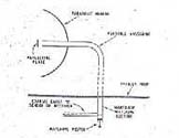
 From
here, the signal is communicated to an oscillator
which contains a crystal detector that converts the wave energy into electrical
signal. A saw-tooth pulse corresponding to the original channel pulse
is generated. The separator unit uses a system of gates
that relate to the number of channels available, in this case eight. The
pulses are superimposed on a monitor, a cathode ray tube to allow the
operator to position the gates in an accurate position over the related
pulse. Click on the speaker to listen to Trevor Ramm’s response to
the use of a cathode ray tube in the WS10. From
here, the signal is communicated to an oscillator
which contains a crystal detector that converts the wave energy into electrical
signal. A saw-tooth pulse corresponding to the original channel pulse
is generated. The separator unit uses a system of gates
that relate to the number of channels available, in this case eight. The
pulses are superimposed on a monitor, a cathode ray tube to allow the
operator to position the gates in an accurate position over the related
pulse. Click on the speaker to listen to Trevor Ramm’s response to
the use of a cathode ray tube in the WS10.
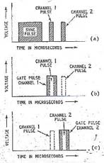
The gates
are timed to coincide with the time duration of their corresponding pulse
and so discriminate against data being transmitted on other channels.
The diagram on the right illustrates how the electrical pulse is ‘captured’
by the gate before the following pulse is able to cause signal interference.
Though each channel transmits its data in rapid succession, the separator
uses the synch pulse to determine when to open and when to close the appropriate
gate; each gate only opens once per cycle, barring all the pulses that
lie outside this band. The modulated electrical pulse can now amplified
and routed to the appropriate telephone line.

|